What you’ll learn:
- How to create an application-optimized thin force sensor.
- How the sensor was integrated with a standard RFID IC.
- The various tests run for accuracy and range under different scenarios.
Some innovations are the result of basic breakthroughs in science or engineering, while others are the result of the merging of different technologies and leveraging their synergistic benefits. The latter is demonstrated by an ultra-thin force-measurement “sticker” (appropriately dubbed “ForceSticker) developed by a team at the University of California San Diego (UCSD).
Applications for their ForceSticker include medical and industrial situations. For example, they could be used in knee implants to measure the forces that implants exert on the joint to monitor an implant’s fit, wear, and tear. They could also be placed on the bottom of warehouse packages to measure the weight of their contents to function as miniature scales. Estimated production cost would be around $2.
Key ForceSticker Components
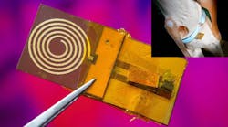
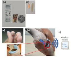
The device consists of two main components: a tiny capacitor that’s just a few millimeters thin and about the size of a grain of rice, and a commercial 900-MHz UHF RFID IC sticker (Fig. 1). The researchers integrated these two components so that they can measure the applied force and communicate the information wirelessly to a standard RFID reader.
1. (a) Two versions of ForceSticker, integrated with standard RFID stickers and a small flexible PCB. (b) The sensor by itself, compared to a rice grain. (c) Demonstrating the flexibility of the sensor PCB designed. (d,e,f) How the ForceSticker can be used for in-vivo implant-force sensing and read wirelessly via a remotely located reader.
The capacitor is made of a soft polymer sheet sandwiched between two conductive copper strips. When an external force is applied, the polymer compresses, drawing the copper strips closer together, thereby increasing capacitance. They designed and evaluated the sensor transduction function based on the optimized capacitive range design derived from mathematical RF modeling, as well as performing multiphysics simulations in COMSOL.
This increase in capacitance is a result of applied force changes in the signal transmitted by the RFID sticker. An RFID reader remotely measures these changes and translates them into a specific magnitude of applied force.
They used two different 4- × 2-mm sensor implementations with differing polymer layers of Ecoflex (a biodegradable platinum-catalyzed silicone-based polymer) and neoprene rubber, to cover ranges of 0 to 6 N and 0 to 40 N, and with readout errors of 0.25 N and 1.6 N, respectively. They also stress-tested the ForceSticker with over 10,000 force applications without seeing any significant error degradation.
The battery-free RFID sticker uses backscattering for power and data transfer. It takes incoming radio signals from an RFID reader, modifies the signals via electric changes induced by the capacitor, and then reflects the modified signals back to the reader, which deciphers and translates them into applied force.
Their approach directly inserts the analog RF phase transformations created by sensor into the wireless channel path of RFID tag. This creates an analog-digital backscatter link, since the RFID tag has a unique digital tag identity, and its analog wireless channel has the force information. To achieve the sensor integration without loss in signal fidelity, the sensor interfacing is done with matched impedance co-planar waveguides.
Sensitive Capacitive Sensor
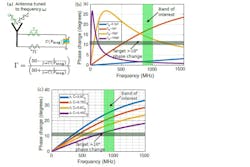
Among the many factors they modeled was the critical value of the sensor capacitance. Since the relationship between capacitance and phase changes is nonlinear, the capacitive sensor had to be designed to operate in a sensitive range, where the phase shifts are large and measurable. Further, it needed to tune the capacitance value such that the nonlinear equation sensitivity is exploited in the desired frequency band of 900 MHz for the commercial UHF RFIDs.
To obtain this sensitivity tuning, the capacitor must have a correctly designed “nominal value” at zero applied force. This was determined by various nonlinear equations that modeled the situation and took into account the impedance of the transmission line and the reflection coefficient (Fig. 2).
2. (a) Reflection coefficient equation. (b) How different values of nominal capacitance 𝐶0 affect Δ𝜙, plotted at a constant Δ𝐶 = 0.75𝐶0. (c) How different Δ𝐶 values affect maximum phase shift attainable, plotted at constant 𝐶0 = 1 pF.
When interfacing with an RFID IC, the sensor must be placed in between the antenna and RFID IC, since the RFID IC is a single-port device and signals don’t pass through it. However, the sensor modeling and characterization shows that there are two so-called “degenerate” solutions (meaning that at least one of the basic variables is zero) (Fig. 3).
3. Interfacing the analog capacitive sensor with digitally identified RFIDs is done by inserting the sensor between the antenna and RFID IC connected in parallel to both. (a) shows what could be a degenerate solution to reflection equation, but capacitive phase transduction doesn’t work this way, while (b) shows the actual mode of operation of the capacitive transduction.
The one represented by the figure on the left assumes that all of the phase change is directly reflected off the sensor with no signals reaching the RFID block. The one on the right assumes that the sensor passes the signals through as well as gives the phase changes, and thus can work with the RFID IC.
They found that the first scenario doesn’t happen in reality, and the sensor actually provides phase changes even in the through mode on the right. Instead of the mathematical model, they showcased the sensor working in through mode via RF-level simulations, which allows it to be integrated easily with RFID ICs.
There were also issues to overcome in data demodulation associated with the deterministic frequency-hopping and associated phase shifts of the RFID arrangement. These are dictated by FCC requirements whereby the readers need to change their frequencies after every 200 ms to avoid interference with other readers in the environment. The standard RFID readers introduce a random phase offset due to hopping, as the phase-locked loop (PLL) locks to a different frequency, and this inadvertently shows up as phase jumps in the phase calculations
Two Test Scenarios Close the Loop
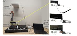
Testing of the device has two distant aspects: one for sensing performance, the other for range. The setup for the first parameter consists of a linear actuator that applies forces on the sensor via an indenter. The three somewhat different ForceSticker prototypes (test platform with rigid PCB and dipole antenna, flexible PCB with spiral antenna, and a standalone RFID sticker) were mounted interchangeably on the load-cell platform (Fig. 4).
4. (a) Experimental setup showing the sensor load cell setup, RFID reader, and actuator. (b) The sensor under test can be either of the three design platforms for ForceSticker: rigid PCB+dipole antenna (b.i), standalone RFID (b.ii), and flexible PCB with spiral antenna (b.iii).
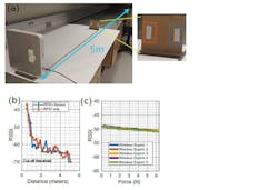
For the distance set of tests, they compared an unaltered RFID IC without the sensor with an RFID IC that’s integrated with the analog capacitive sensor (Fig. 5). They took signal-strength readings from 0 to 5 meters from the RFID reader antenna and plotted the readings. The RFID with sensor could not be read beyond 4.6 m, while the standard RFID reached 4.8 m, which is only slightly more than capacitive sensor plus RFID.
5. (a) They moved the cardboard plate away in steps of 20 cm from 0.5 to 5 m distance from the RFID reader antenna. The cardboard plate has two RFIDs: a “plain” RFID (orange box) and a standalone ForceSticker RFID ForceSticker (blue box). (b) Both the blue and orange RFIDs show similar received signal strength indicator (RSSI) drops. (c) RSSI of the RFID’s wireless channel doesn’t degrade noticeably because of applied force, unlike the channel phases. Together, (b) and (c) show no adverse effect on the RFID wireless channel’s RSSI, and hence the reading range of both orange and blue RFIDs are similar.
They also did several case studies. For the first one, they placed the flexible PCB ForceSticker platform with spiral antenna beneath the knee joint in a toy-knee model and applied forces onto the sensor by pressing on the top of the knee bone manually (Fig. 6).
6. (a) Test setup. (b) Zoomed image to show the flexible PCB ForceSticker snugly fit within the knee-joint. (c) ForceSticker’s wireless force readings correlates well with the force readings from the load cell placed below the knee.
The small-size form factor of ForceSticker sensor fits inside the knee joint without disturbing the joint at all and is almost unnoticeable if viewed from a distance. To see if the sensor could detect the applied forces, they applied forces of roughly 1 N, 3 N, and 5 N force in steps delayed by 20 seconds.
As noted previously, while reading range was approximately 5 m through air, they also did an in vivo test. For this, they used a pork belly setup to replicate in-body sensing and found that the range was about 10 cm. In addition, they tested with people moving around the sensor-device to showcase the robustness of phase sensing to both reduced signal strengths and dynamic multipath.
The team also acknowledged the limitations of their design. At present, the stickers require a static environment to function effectively and don’t perform optimally in highly dynamic surroundings. The researchers are actively addressing this issue as they seek to further improve the technology.
Their work is detailed extensively in the paper “ForceSticker: Wireless, Batteryless, Thin & Flexible Force Sensors,” published in Proceedings of the ACM. At 35 pages, it’s the longest “equation-light” academic paper of this type I’ve ever seen. It even includes a helpful table comparing their approach to various alternative techniques that address the general constrained-area force-sensing problem and the relative pros and cons of each.
