With all the features they pack, smartphones are becoming more power hungry and can drain a battery in no time. This is one of the most common problems which smart phone users face today. Manufacturers try to pack bigger batteries to extend operating life but there are limitations due to the weight and size of the battery. Imagine the situation where your smart phone runs out of power in the middle of the road when you are using it for navigation. At this moment, all you need is a power source to charge your phone but unfortunately there is none nearby.
Portable Energy
A power bank is a portable energy source that can be carried in your pocket or backpack. It stores energy in its internal Lithium Ion battery and can provide this power to charge your portable device like smart phones and tablets when the need arises.
In the first part of this article, we’ll discuss the basics of a power bank, various specifications, and features available in the power banks. In the second part of this article, we’ll describe the implementation of a power bank in detail.
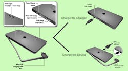
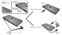
Fig. 1 shows the various parts of a power bank. The power bank has a switch to turn on the power bank and charge a mobile device. The status LEDs indicate the amount of charge left in the power bank and also indicate charging/discharging operation. A Micro-USB connector is used to connect the charging source to charge the internal battery. The power bank can either be connected to a PC/Laptop or to a wall power source to charge the battery. A USB-A connector is used to connect the mobile device for charging.
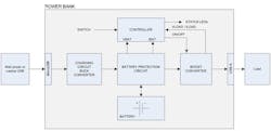
Fig. 2 shows a high level block diagram of the power bank. The main component of the power bank is a lithium-ion battery that stores energy. The battery is first connected to a battery protection circuit that continuously monitors the battery voltage and current, and disconnects the battery in case of various events like over charge, over discharge, over load, and short circuit.
The input voltage from the Micro-USB connector is fed to a charge controller. This is usually a buck converter that converts the 5 V input voltage into either a constant current or constant voltage to charge the lithium-ion battery.
The boost converter converts the battery voltage – which can range from 3.0 V to 4.2 V – up to 5 V, the voltage used to charge external mobile devices.
A microcontroller performs control functions like turning on the boost converter when the switch is pressed, measuring the battery voltage, controlling the LEDs to indicate state of charge, and turning off the boost converter when the external mobile device stops drawing current.
Now let us take a detailed look at each of these blocks.
Charge Controller
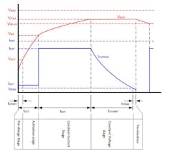
The charge controller implements the charging algorithm to charge the internal lithium-ion battery. It is usually based on a buck converter topology. The charging process passes through several stages to charge the battery to its full capacity while at the same time ensuring the battery is charged safely. During these stages, the battery has to be charged using either a Constant Current (CC mode) or a Constant Voltage (CV mode). Fig. 3 shows the various stages involved in charging a lithium-ion battery, including:
1. Pre-charge– Charging begins with a pre-charge stage to check if the battery is in good condition.
2. Activation– If the battery is deeply discharged and if the voltage is below VRS, the battery is charged with a very low constant activation current IACT – which is around 1/50 of the battery mAH rating – untll the battery voltage crosses the VRS threshold. This stage is called the activation stage.
3. Constant current– Once the battery voltage is above VRS, the battery is charged with the main charge current – 0.5C or 1C – in constant current mode. This state is maintained until the battery voltage rises to full charge voltage VFULL, which is typically 4.2 V + 0.05 V.
4. Constant voltage– When the battery voltage reaches its full charge voltage, charging is switched to constant voltage charge where the battery voltage is maintained at 4.2 V. While the battery voltage is maintained constant, the current through the battery drops. When the current reaches a predetermined threshold ITERM, charging is terminated. Optionally, some chargers apply a top off charge when the battery voltage drops to 4.05 V.
Battery Protection Circuit
Lithium-ion batteries are extremely hazardous if not handled properly. When the voltage of the battery is allowed to rise beyond 4.2 V, the battery grows hot. There have been numerous incidents where Lithium ion batteries have caught fire because of poor protection logic. Thus, from a safety point of view, battery protection becomes extremely important. The battery protection circuit implements some or all of the following protections:
· Over charge protection – Disables charging when the battery voltage goes above a safe threshold
· Over discharge protection – Disables discharging when the battery voltages goes below a threshold
· Short circuit protection – Disables discharging if a short circuit is detected
· Temperature protection – Disables charging and discharging if the battery temperature goes above or below pre-determined thresholds.
Boost Converter
Lithium-ion battery operating voltage typically ranges between 3.0 V to 4.2 V and almost all of the mobile phones available need 5 V for charging. The boost converter steps up the 3.0 V to 4.2 V battery voltage to the 5 V required to charge mobile devices.
Controller
The controller in a typical power bank performs basic housekeeping tasks. Some of the tasks performed by controller in a power bank are as follows:
· Detect if the switch has been pressed and enable output of the boost converter.
· Measure the current drawn by the load and turn off the boost converter when the load stops drawing current.
· Measure the battery voltage and drive the status LEDs to display battery level during charging and discharging.
Features of Power Banks
Now that we covered the high-level functions of a power bank, let us have a look at some of the important features of the power bank.
Maximum load current – This is the maximum current the power bank can supply to a mobile device for charging. Different mobile devices need different charging currents. For example, iPhones charge with a maximum of 1 A, iPad2s draw 2.1 A, iPad4s draw 2.4 A, and android devices can draw currents from 0.5 A to 1.5 A.
Output voltage – This is the voltage available at the output of the power bank to charge mobile devices. Most mobile devices need an output voltage of 5 V + 0.25 V to charge.
Charging current – This is the maximum current that the power bank draws to charge the internal Lithium Ion battery. Typical currents drawn by power banks are 0.5 A and 1 A.
Auto detection of charging source – It is possible to charge the internal Lithium ion battery of the power bank through various sources like a PC / Laptop or wall powered adaptors. Before we delve further into this, let us have a look at various charging sources as defined by Battery Charging Specifications BC1.2
· SDP (Standard Downstream Port)– This is the regular USB port present in desktop PCs and laptops. As per the USB specification, a peripheral can draw up to 500 mA after enumeration. Without enumeration, a peripheral can only draw 100 mA of current. If a device tries to draw more than 500 mA of current, this could lead to a BSoD (Blue Screen of Death) or port failure.
· CDP (Charging Downstream Port)– This is a special USB port present in some PCs. This USB port can provide a current of up to 1.5 A to peripherals.
· DCP (Dedicated Charging Port)– This is a USB port meant only for charging and does not perform any communication functions. This port can supply up to 1.5 A of current to a charging device.It is important to distinguish between the type of charging source the power bank has been connected and draw the appropriate power. For example, if the power bank is connected to a PC, it should not draw more than 100 mA of current. On the other hand, if it has been connected to a DCP, the power bank can draw up to 1.5 A to charge its internal battery.
Support Multiple Mobile Device Types
Today’s smart phones have a common port for communication and charging. Based on the type of charging port they are connected to, these phones decide the amount of current to be drawn. For example, if a phone is connected to the USB port of a PC, it enumerates and draws 100 mA or 500 mA of current, but if it is connected to a wall power charger, the phone draws a higher current to charge the battery at a faster rate.
In order for the phone to be able to differentiate between a wall power charger and USB host, phone manufacturers use various voltage levels on the D+ and D- signals of the USB connector. Based on these voltage levels, the phone draws the appropriate charging current.
These voltage levels are different for different devices. In general, Apple devices (also known as MFi devices) follow a particular bias level, and all Android devices follow another bias level.
This makes it difficult for power banks to be able to support MFi and Android devices on the same port. In low-cost power banks, manufacturers usually get around this problem either by providing two output USB ports (one with bias levels for MFi devices and another with bias levels for Android devices) or by providing charging cables which have biasing networks molded inside the cables. Some high-end power banks support automatic detection of the mobile device and appropriately bias the D+ and D- lines, thus supporting all devices on a single output port.
Boost Converter Efficiency
The efficiency of the boost converter is the ratio of the amount of power delivered to a charging mobile device to the amount of power drawn from the internal battery. The higher the efficiency, the more energy the power bank provides to charging devices for the same battery capacity. The efficiency of the boost converter depends on the selection of components like MOSFETs, inductors, and diodes, as well as the way the PCB has been laid out to minimize losses. Good power banks typically have an efficiency of 85% or above, with more being better.
No-Load Detection
Another important feature of a power bank is to detect when the charging mobile device has stopped drawing current (i.e., when the mobile device is fully charged) and disable the boost converter. Without this feature, even after the mobile device is fully charged, the boost converter will keep drawing current from the battery – in the range of a few tens of milliamps – and could soon drain the battery.
In this first part, we have looked at the basics of a power bank, detailed a high-level block diagram, and described various features commonly available in power banks. In the next part of this article, we will look into the details of implementing a power bank.


