The TPS548D22 from Texas Instruments is a high-efficiency, synchronous buck converter suitable for applications with loads up to 40 A (Fig. 1). It does not employ monolithic MOSFETs because they are not capable of providing the necessary low RDS(ON) and high efficiency at 40 A in a small footprint . Therefore, a multi-chip module (MCM) with monolithic control and drive circuitry and two discrete N-channel NexFET power MOSFETs were used to provide low resistivity for 40 A loads with high power density, high efficiency, and small PCB layout area. With a nominal 5V gate voltage (VGS) typical on-resistance, RDS(ON), is 2.9 mΩ, for the high-side MOSFET and 1.2 mΩ for the low-side MOSFET. These MOSFETs have drain-to-source breakdown voltage of 25 V DC and can handle a 10ns, 27 V transient.
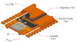
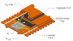
Figure 2 shows the internal construction of the TSP548D22’s LQFN-CLIP (RVF) package. Called “Powerstack,” it uses clips to hold the high-side and low-side power MOSFETs. (LQFN is a low-profile QFN package.)
This buck converter is intended for high accuracy, fast transient response, ease-of-use, low external component count, and space-conscious power systems. The converter input voltage range is from 1.5 V up to 16 V, and the VDD input voltage range is from 4.5 V to 22 V. The output voltage range is adjustable from 0.6 V to 5.5 V. It features an accurate 0.5%, 0.9 V reference over a junction temperature range of –40°C and 125°C, and full differential remote voltage sense to provide very high overall regulation accuracy.
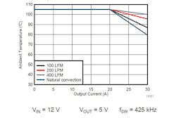
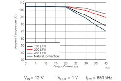
Figure 3 is the safe operating area (SOA) as indicated by a plot of output current vs. ambient temperature for 12VIN and 5VOUT for the TPS548D22. Figure 4 is the SOA plot of output current vs. ambient temperature for 12VIN and 1VOUT for the TPS548D22. Data was derived using the TPS548D22’s evaluation module.
Overtemperature protection (OTP) monitors the IC’s die temperature. If the temperature exceeds the threshold value (default value 165°C), the TPS548D22 shuts off. When the temperature falls about 25°C below the threshold value, the IC turns on again. OTP is a non-latch protection. TPS548D22 also offers a choice of hiccup or lath-off OCP.
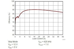
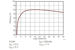
The FSEL pin programs light-load selection, which can be either SKIP mode or FCCM (forced continuous current mode) that “fixes” the frequency to reduce noise vs. DCM (discontinuous current mode) that provides pulse skipping for improved efficiency under light load conditions. For optimized light-load efficiency, you should program the IC to operate in SKIP mode. For better noise/ EMI performance from no load to full load, it is recommended to program the device to operate in FCCM mode. Figure 5 is a plot of efficiency vs. load current for the SKIP mode and Fig. 6 is efficiency vs. load current for FCCM operation.
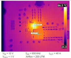
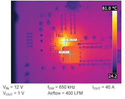
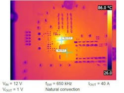
A TPS548D22 evaluation module was used to check the device temperature. Figures 7a, 7b, and 7c are thermal photographs when cooling device at 200, 400 LFM and natural convection with 12VIN and 1VOUT, and 650kHz switching frequency.
Architecture
The TPS548D22 uses an improved D-CAP3 control-loop architecture that incorporates a steady-state error integrator. The slow integrator improves the output voltage dc accuracy greatly and presents minimal impact to small-signal transient response. To further enhance the small-signal stability of the control loop, the device uses a modified ramp generator that supports a wider range of output LC stage as well as a function of selected switching frequency (fSW) and the duty cycle (VOUT-to-VIN ratio). In addition, provisions are made to fine-tune the internal ramp amplitude.
RSP (+) and RSN (-) pins are used for remote sensing. When feedback resistors are required for output voltage programming, the RSP pin should be connected to the mid-point of the resistor divider and the RSN pin should always be connected to the load return. In the case where feedback resistors are not required (when the VSEL programs the output voltage set point), the RSP pin should be connected to the positive sensing point of the load and the RSN pin should always be connected to the load return. RSP and RSN pins are extremely high-impedance input terminals of the true differential remote sense amplifier, so the feedback resistor divider should use resistor values much less than 100 kΩ.
Adaptive on-time control allows selectable frequency settings of 425 kHz, 650 kHz, 875 kHz, or 1.05 MHz. Higher frequencies allow smaller value inductors and output capacitors compared to a power supply that switches at a lower frequency. However, the higher switching frequency causes extra switching losses, which decrease efficiency and impact thermal performance. Here, a moderate switching frequency of 650 kHz achieves both a small physical size and a high-efficiency operation with the frequency selected.
Soft-start time controls the inrush current required to charge the output capacitor bank during startup. The device offers selectable soft-start options of 1 ms, 2 ms, 4 ms, and 8 ms. When the device is enabled (either by EN or VDD UVLO), the reference voltage ramps from 0 V to the final level defined by VSEL pin strap configuration, in a given soft-start time. The TPS548D22 device supports soft-start times between 1msec and 8msec selected by MODE pin configuration.
A power-good output registers high when switcher output is within the target. The power-good function is activated after soft-start has finished. When the soft-start ramp reaches 300 mV above the internal reference voltage, the PGOOD detection function is enabled. If the output voltage becomes within ±8% of the target value, internal comparators detect power-good state and the power-good signal goes high after a PMBus programmable delay. If the output voltage is outside of ±16% of the target value, the power-good signal becomes low after 2 μs internal delay. The open-drain power-good output must be pulled up externally. The internal N-channel MOSFET does not pull down until the VDD supply is above 1.2 V.
Layout Guidelines
- It is absolutely critical that all GND pins, including AGND (pin 30), DRGND (pin 29), and PGND (pins 13, 14, 15, 16, 17, 18, 19, and 20) are connected directly to the thermal pad underneath the device via traces or plane.
- Include as many thermal vias as possible to support a 40 A thermal operation. For example, a total of 35 thermal vias are used (outer diameter of 20 mil).
- Place
dthe power components (including input/output capacitors, output inductor, and TPS548D22) on one side of the PCB (solder side). Insert at least two inner layers (or planes) connected to the power ground, in order to shield and isolate the small signal traces from noisy power lines. - Place the VIN pin decoupling capacitors as close to the PVIN and PGND pins as possible to minimize the input ac current loop. Place a high-frequency decoupling capacitor (with a value between 1 nF and 0.1 μF) as close to the PVIN pin and PGND pin as the spacing rule allows. This placement helps suppress the switch node ringing.
- Place VDD and BP decoupling capacitors as close to the device pins as possible. Do not use PVIN plane connection for the VDD pin. Separate the VDD signal from the PVIN signal by using separate trace connections. Provide GND vias for each decoupling capacitor and make the loop as small as possible.
- Ensure that the PCB trace defined as switch node (which connects the SW pins and up-stream of the output inductor) are as short and wide as possible. In the TPS548D22EVM-784 EVM design, the SW trace width is 200 mil. Use a separate via or trace to connect SW node to snubber and bootstrap capacitor. Do not combine these connections.
- Place all sensitive analog traces and components (including VOSNS, RSP, RSN, ILIM, MODE, VSEL, and FSEL) far away from any high-voltage switch node (itself and others), such as SW and BOOT to avoid noise coupling. In addition, place MODE, VSEL, and FSEL programming resistors near the device pins.
- The RSP and RSN pins operate as inputs to a differential remote sense amplifier that operates with very high impedance. It is essential to route the RSP and RSN pins as a pair of diff-traces in Kelvin-sense fashion. Route them directly to either the load sense points (+ and –) or the output bulk capacitors. The internal circuit uses the VOSNS pin for on-time adjustment. It is critical to tie the VOSNS pin directly tied to VOUT (load sense point) for accurate output voltage result.
The IC is available in a 5 mm x 7 mm QFN-type package with 40 power and I/O pins. It employs TI’s proprietary MCM packaging technology with a thermal pad. With a properly designed system layout, applications achieve optimized safe operating area (SOA) performance.
