This video/article is part of Dostal's Designs series in Ideas for Design and the TechXchange: Power Supply Design. You can also post a question.
Members can download this article in PDF format.
What you'll learn:
- Using a current limiter in boost converters for circuit protection.
- An easy-to-implement design idea to achieve the desired current limiting.
Currents often have to be limited in electronic circuits. For example, in a USB port, excessive current flow must be prevented so that the electrical circuit can be reliably protected. Likewise, in a power bank, it’s critical that battery discharge be prevented. Discharging with too high of a current can lead to an impermissibly high voltage drop in the battery and an insufficient supply voltage to the downstream device.
Thus, it is often necessary to limit a current flow to a specific value. Most power converters have overcurrent limiters to protect themselves from damage due to excess currents. In some dc-dc converters, the threshold can even be adjusted.
In Figure 1, a dc-dc boost converter with a built-in, possibly even adjustable, current limiter could also be used. In this case, the additional current-limiter block may be omitted. However, there are also many applications that don’t use a dc-dc converter in the power path.
One such example is when a voltage of 24 V is available in a system and the current flow in this line should be limited, but the load must be operated at exactly 24 V. In this case, an additional current-limiter block, as shown in Figure 1 in blue, can be used. A current-limiter circuit comes from the family of protection modules that includes hot-swap controllers, surge protectors, electronic-circuit protectors, and ideal diodes.
Most of these ICs on the market use external MOSFETs as switches to switch the current flow on and off, but also to limit the current, in which case the switch works like a linear regulator. However, such a switch must ensure that the MOSFET is always operated within its safe operating area (SOA). If this isn’t the case, the semiconductor and thus the circuit will be damaged.
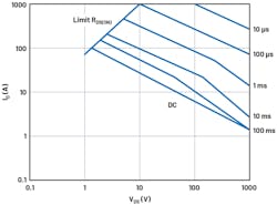
Unfortunately, it’s not always easy to select a suitable MOSFET and operate it in just such a way that it never leaves the SOA. The operating temperature, voltage, current, and especially the time are all factors that influence this setup. They all have to be right to ensure safe operation. Figure 2 shows an SOA diagram for a typical N-channel MOSFET. Operation of the MOSFET below the lines shown is permitted.
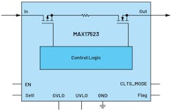
Figure 3 shows a dedicated current-limiter IC, the MAX17523 from Analog Devices. It has two MOSFETs that can limit current to a value between 150 mA and 1 A. If the current flow reaches the limit, it’s either cut off and resumed after a certain waiting period. Otherwise, the current flow is interrupted continuously until the next switch-on, or the current is limited through a reduction in voltage. The internal MOSFET is then operated in the ohmic region, which is a type of linear regulator function.
In each of these adjustable limitation modes, the internal MOSFET is always in its SOA and isn’t damaged. And no elaborate calculations or evaluations are required.
Limiting currents in a circuit isn’t a problem if suitable highly integrated ICs are used. It also makes sense to combine this type of circuit with a dc-dc converter if the converter doesn’t have an adjustable current limiter.
View/read more video/articles in the Dostal's Designs series in Ideas for Design and the TechXchange: Power Supply Design. You can also post a question.


