Design and manufacture of a high-powered µModule requires attention to both the mechanical and electronics features of the product. This was the case with the LTM4700 Power µModule regulator, which is a non-isolated step-down dc-dc power regulator with PMBus interface developed by Analog Devices.
The device can be configured with either a dual 50A or single 100A output. It employs analog and digital mixed-signal technology along with innovative packaging technology. Thus, it represents a good example of combining electronic and mechanical design techniques to achieve a high-performance module with minimum footprint.
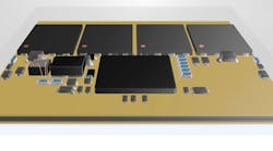
It took about 4½ years to develop the technology associated with cooling and packaging the LTM4700 µModule regulator. The package itself is overmolded to allow for insertion of the electronics as well as the cooling features. A small internal circuit board contains the electronic components (Fig. 1).
1. This small circuit board contains the regulator’s internal components. The two pairs of synchronous MOSFETs are in the back and the control IC is in the front. Inductors (two-in-one) pull heat from MOSFETs to the top of the µModule device for faster cooling.
The company designed the regulator’s two inductors with a special case that helps to cool the nearby MOSFETs on the circuit board. Miniature copper piping and a cold plate aid in removing conducted heat from the device. When the design was completed, thermal modeling and many thermal photos were taken to ensure it was cooled adequately. And, the package is shaped so that forced-air cooling can effectively cool the µModule. In addition, the cooling techniques were developed with an eye on cost-effective manufacturing.
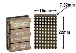
As a result of the cooling technique employed in the LTM4700, the module’s size is a mere 15 × 22 × 7.87 mm in a BGA package (Fig. 2). This µModule operates at 73°C using its unique packaging technology. In contrast, modular solutions typically run at 90°C. Peak conversion efficiency at 12VIN to 0.8VOUT reaches 90%. Its architecture also enables combining up to eight devices to power an 800A load.
2. The LTM4700 package can deliver 100A at 12VIN to 0.8VOUT with 200 LFM air flow up to 70°C ambient temperature.
Integrated Circuits
The LTM4700 is a highly integrated component-on-package design that includes onboard memory, data-conversion circuitry, and digital interface, packaged in a way that produced a device nearly half the size of similar devices. When installed in a data center, this smaller power source will increase server density, which can boost throughput and computational power. And, the power source will have minimal impact on system size and cooling costs.
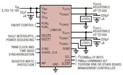
The LTM4700 operates from a 4.5V to 16V input range, with output voltages digitally controlled from 0.5V to 1.8V (Fig. 3). Integrated analog-to digital converters (ADCs), digital-to-analog converters (DACs), and EEPROM enable users to digitally monitor, record, and control power parameters using an I²C PMBus interface. Switching frequency is synchronized to an external clock from 200kHz to 1MHz for noise-sensitive applications. The LTM4700 also has self- and load-protection features against fault conditions such as overvoltage and undervoltage, overcurrent, and overtemperature.
3. The LTM4700 µModule regulator employs two integrated synchronous power MOSFETs with 50A outputs.
Included in the LTM4700 is a built-in EEPROM with ECC and I2C-based PMBus/SMBus 2-wire serial communication interface capable of 400kHz SCL bus speed. You can set the two output voltages with a few external resistors. Readback telemetry data of input and output voltages and input and output currents, as well as module temperatures, are continually digitized cyclically by an integrated 16-bit ADC. Many fault thresholds and responses are customizable. Data can be autonomously saved to EEPROM when a fault occurs, and the resulting fault log can be retrieved over its I2C port at a later time for analysis.
The LTM4700’s 2-wire serial interface enables outputs to be margined, tuned and ramped up and down at programmable slew rates with sequencing delay times. Input and output currents and voltages, output power, temperatures, uptime, and peak values are readable. At startup, output voltages, switching frequency, and channel phase angle assignments can be set by pin-strapping resistors.
An external resistor configures the frequency of the SYNC clock (switching frequency) and the channel phase relationship of the channels to each other and with respect to the falling edge of the SYNC signal. Most possible combinations of switching frequency and phase-angle assignments are programmable by a resistor.
The LTM4700 module also has sufficient stability margins and good transient performance with a wide range of output capacitors, even all-ceramic MLCCs. Analog Devices’ LTpowerCAD tool is available for transient and stability analysis, and experienced users who prefer to adjust the module’s feedback-loop compensation parameters can use this tool.
Demo Board
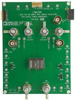
The DC2702A-A dual-output, high-efficiency, high-density demo board uses the LTM4700 μModule regulator (Fig. 4). Each output can supply 50A maximum load current. The demo board powers up to default settings and produces power based on configuration resistors, without the need for any serial bus communication.
4. The LTM4700 demo board supports a variety of different tasks, such as evaluating the LTM4700 µModule circuit and running diagnostics.
To fully explore the extensive power-system management features of LTM4700, download the GUI software LTpowerPlay onto your PC and use LTC’s I2C/SMBus/PMBus dongle DC1613A to connect to the board. LTpowerPlay is a Windows-based development environment supporting Analog Devices' Digital Power System Management (PSM) products.
LtpowerPlay supports a variety of different tasks, such as using it to evaluate modules by connecting to a demo-board system, and in an offline mode (with no hardware present) to build a multichip configuration file that can be saved and reloaded at a later time. It also provides diagnostic and debug features, and becomes a valuable diagnostic tool during board bring-up to program or tweak the power-management scheme in a system or to diagnose power issues when bringing up rails.
Features
The LTM4700 offers:
- ~90% Full Load Efficiency from 12VIN to 1VOUT at 100A
- ±0.5% Maximum dc output error over temperature
- ±3% current readback accuracy (25°C to 125°C)
- Soft-start actively regulates the load voltage while digitally ramping the target voltage from 0V to the commanded voltage set-point
- Integrated input current-sense amplifier
- 400kHz PMBus-compliant I2C serial interface
- Supports telemetry polling rates up to 125Hz
- Integrated 16-bit ΔΣ ADC
- Time-based mode for sequencing the outputs on and off
- Constant frequency current-mode control
- Digital power system management simplifies and accelerates power system characterization, optimization, and data mining during prototyping, deployment, and field operation
- Parallel and current share multiple modules
Fault Detection and Handling:
- Input OV Fault Protection and UV Warning
- Average Input OC Warn
- Output OV/UV Fault and Warn Protection
- Output OC Fault and Warn Protection
- Internal control Die and Internal Module Overtemperature Fault and Warn Protection
- Internal Undertemperature Fault and Warn Protection
- CML Fault (Communication, Memory or Logic)
- External Fault Detection via the Bidirectional FAULTn Pins
Readable Data:
- Input and output voltages, currents, and temperatures
- Running peak values, uptime, faults, and warnings
- Internal EEPROM and fault logging with ECC
Writable Data and Configurable Parameters:
- Output voltage, voltage sequencing, and margining
- Digital soft-start/stop ramp
- Optimize analog loop compensation
- OV/UV/OT, UVLO, frequency, and phasing


